Derating Current-Carrying Conductors for Conditions of Use

By: Jerry Durham | Aug 05, 2020
If you ask a seasoned electrician how many No. 12 AWG conductors will fit into a 3/4″ EMT conduit system, you may get a response such as  “one more!” While this is amusing (and typically true), there are precautions that must be taken according to the NEC whenever conductors are bundled together in a raceway, cable, or even in a ditch in the earth.
Similar precautions must also be taken where conductors are installed in temperatures above 86°F. Both conditions contribute to heat build-up and poor conductor performance.
We will look at what the 2020 NEC says about these conditions of use by reviewing:
- Section 210.19(A)(1) – Continuous and noncontinuous loads. 125%
- Table 310.16 – Conductor Ampacities
- Table 310.15(B)(1) – Temperatures other than 86°F
- Table 310.15(C)(1) – More than three current-carrying conductors in a raceway, cable, or buried in the earth
Continuous and Noncontinuous Loads – Section 210.19(A)(1)
Section 210.19(A)(1) instructs electricians to size conductors at 100% of the load rating for all noncontinuous loads, plus 125% of the load rating for all continuous loads on the circuit. However, if the electrician must also apply adjustment factors to those conductors from Table 310.15(C)(1) for more than three current-carrying conductors in a conduit, and/or correction factors from Table 310.15(B)(1) for temperatures above 86 degrees Fahrenheit, then the NEC requires us to compare the results from the two requirements and use the larger of the two. In other words, if increasing the conductors by 125% produces the larger conductor, you must use that conductor. But if applying adjustment and correction factors for excessive ambient temperatures and bundling conductors produces the larger conductor, you must use that conductor.
What is the 125% Increase?
Increasing the conductor size 125% for a continuous load serves as an additional heat-sink for the circuit. The larger conductor provides more surface area for heat to be displaced in the circuit and more surface area for heat to be transferred to the surrounding ambient air. The larger conductor takes heat away from the terminals where the conductor is connected. But when the terminals of all components are rated to run 100% of their marked rating, then upsizing the conductor to 125% to serve as a heat-sink is not necessary.
Conductor Ampacity – Table 310.16
Table 310.16 in the 2020 NEC provides conductor ampacities for the wiring we use every day when conditions of use do not force us to deviate from those numbers. Those “conditions of use” usually include ambient temperatures above 86°F, or more than three current-carrying conductors installed together in a raceway, cable, or buried in the earth. Or both.
Table 310.16 is divided into two smaller Tables with copper (Cu) conductors addressed on the left-hand side of the Table and aluminum (Al) and copper-clad aluminum conductors addressed on the right-hand side of the Table. Copper conductors can carry more current than aluminum conductors of the same size.
There are three temperature rating columns provided in the Table: 60°C, 75°C, and 90°C. Most conductors fall into one of these three temperature columns.
Heat is generated inside a conductor as electrical current flows through the conductor. The greater the current flow, the more heat generated in the conductor. The insulation surrounding the conductor, typically thermoset or thermoplastic type insulation, must be rated high enough to withstand that heat. Table 310.16 limits the ampacity of conductors based on their insulation rating. For example a 90°C No. 6 conductor can carry more current than a 60°C No. 6 conductor, not because the wire itself is different, but because the insulation of the 90°C conductor is built to withstand more heat without breaking down. When the generated heat inside the conductor exceeds the insulation rating of the conductor, the insulation surrounding the wire can discolor, become brittle, and may eventually fall off.
If you have ever seen a white grounded conductor that has a brown tint to its insulation, you were looking at a conductor being used at an ampacity higher than its rating.

We understand that heat is generated as current flows through the conductor, and how important it is for a conductor’s insulation to be able to safely withstand that heat without breaking down. But another type of heat exists that is equally important to conductor longevity- ambient temperature. Ambient temperature is the air temperature surrounding your electrical conductors after installation. When that is too high, it is bad news for the conductor.
Ambient Temperatures Other than 86°F – Table 310.15(B)(1)
If the temperature surrounding a conductor is above 86°F, the heat being generated inside the conductor during normal use cannot dissipate effectively through the insulation. If the heat cannot effectively escape the conductor, then we must decrease the amount of current flow on the conductor to reduce the heat being generated in the conductor.
This reduction in allowed current flow on a conductor due to ambient temperatures above 86°F is called “ambient temperature correction”, and it requires correction factors from Table 310.15(B)(1) to be used in conjunction with the values from Table 310.16.
The correction factors in Table 310.15(B)(1) are percentages, and they are applied to the normal ampacity values provided in Table 310.16 to reduce their value. For example, a THWN No. 6 copper conductor from Table 310.16 is stated to be worth 65 amps. But according to Table 310.15(B)(1), when that same conductor is installed in an ambient temperature ranging between 105°F – 113°F, it is only worth 82% of its value, or 53.3 amps. (65 x .82 = 53.3)
Not only must the electrician be concerned with ambient temperatures degrading and causing poor performance in a conductor, but the electrician must also be wary of installing too many current-carrying conductors together in a raceway, cable, or buried in the earth. Installing more than three current-carrying conductors together in a single raceway, cable, or covered ditch has the same destructive effect on a conductor’s insulation as installing conductors in an elevated ambient temperature.
More Than Three Current-Carrying Conductors in a Raceway, Cable, or Earth – Table 310.15(C)(1)
Table 310.15(C)(1) requires conductors to be derated whenever more than three current-carrying conductors are installed together in a raceway, cable, or in a covered ditch in the earth. For example, Table 310.15(C)(1) requires a THWN No.4 copper conductor, normally valued at 85 amps according to Table 310.16, to be derated to 80% of its value when there are 4-6 current-carrying conductors bundled together. The same conductor must be derated to 70% of its normal value when there are 7-9 current-carrying conductors bundled together, and so on. The ampacity of conductors continues to decrease in Table 310.15(C)(1) as the number of conductors bundled together increases.
When more than three current-carrying conductors are installed together in a single raceway, cable, or covered ditch, the ampacity of each conductor must be reduced according to the applicable adjustment factor from Table 310.15(C)(1). Reducing the current flow in each conductor reduces the heat generated in each conductor. Collectively, this reduces the overall operating temperature of the wiring in the conduit system and saves the conductor insulation from premature failure.
A conductor’s insulation degrades over time even with normal use. But when the conductor is subjected to temperatures beyond the conductor’s rating, that failure occurs much sooner. A conductor used under normal conditions and according to the manufacturer’s instructions can provide decades of reliable service.
What is a Current-Carrying Conductor?
Remember, Table 310.15(C)(1) applies only to current-carrying conductors and NOT every conductor is a current-carrying conductor.

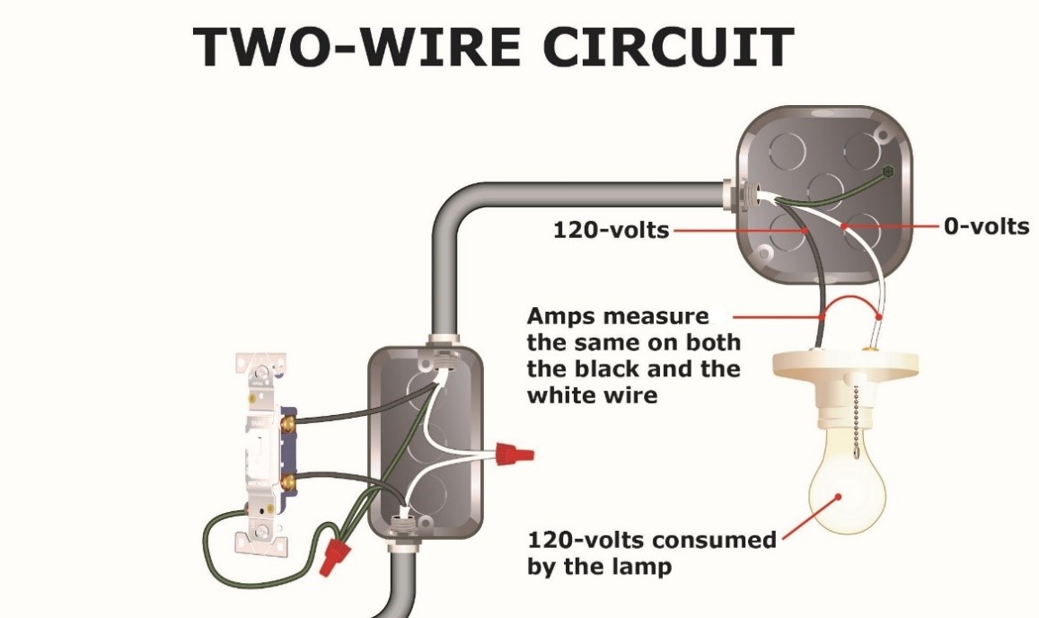
Section 310.15(F) states that a grounding or bonding conductor (typically bare or green in color) is never counted as a current-carrying conductor. However, Section 310.15(E) states that the white grounded (neutral) conductor IS a current-carrying conductor if it carries all of the current (amps) in the circuit, such as a two-wire 120-volt circuit serving a lighting fixture. But when the white grounded conductor is serving as a neutral conductor, where it only carries the unbalanced load between two phase conductors serving the same load, it is not a current carrying conductor. The electrician should study Section 310.15(E) to become familiar with the rules for a neutral conductor installed in a conduit.
How Do We Limit the Current?
Repeatedly, we have stated that a conductor’s ampacity is required to be reduced if the conductor is exposed to excessive ambient temperatures or too many current-carrying conductors installed together in a raceway or similar. But how do we reduce that ampacity? How do we limit current flow? Do we get a promise from the customer stating they won’t apply more amps to the circuit than we have advised since the conductor has been derated? Of course not. When we say we are limiting the amps or current flow on a circuit or conductors, we simply mean we are reducing the rating of the overcurrent device.
If a conductor is normally worth 50 amps but ambient temperatures require the conductor to be derated to 80%, we simply must reduce the overcurrent device so that it trips at the new ampacity rating of the conductor.
Remember, reducing a conductor’s ampacity will not always result in a value that aligns with a standard fuse or circuit breaker size from Table 240.6(A). Fortunately, electricians are permitted to move up to the next standard size overcurrent device in the Table whenever a conductor’s rating doesn’t align with the standard values from the Table. This is permitted up to and including 800 amps.


Older wiring from the 70’s era is typical of being overheated. An incandescent light inside a globe or even 2 lights inside a globe can elevate the box temperature above a 75 degree C rating.
I just saw your comment—that is a good observation.
Something else I will add (since you kicked us off) INCANDESCENT LAMPS (The old style resistance filament-type bulbs) rated higher than the wattage of the luminaire (particularly any enclosed fixture that traps the heat) can cause those lamps (bulbs) to burn out within a week or two. Folks try everything BUT lowering the wattage of the bulb to fix the problem. It is as simple as the light bulb filament overheating because the heat (additional heat caused by a higher wattage bulb) can’t escape, and the filament burning in two prematurely. So, it is necessary to mind the wattage rating on the fixture (usually 60 watts).
Thanks!
Jerry Durham – JADE Learning
Thank you for the extraordinarily good explanation. Trying to decipher the NEC is almost hopeless without such good supplementary commentary.
So doesn’t the conduit size make any difference? If I have 4 #12 current carrying conductors in a 4 inch conduit it will require derating?
Correct. The size of conduit does not matter for de-rating purposes.
My electrician is pulling 8 #12 wires for 4 new 20 Amp kitchen circuits through a 1/2″ conduit. How will that derate the amperage of each circuit?
At the very least without doing the calculation, it will require him to derate the # 12 conductors to a value less than 20 amps which would cause another problem. If you keep the # 12 AWG wire size then you would violate the code requirements that require the 20 ampere minimum appliance branch circuit ratings, because of the breaker size he would be required to reduce to. The only way to solve this is to install a larger conductor, or run separate conduits to keep the maximum number of current carrying conductors at 3 or less.
I’m not an expert, but off-hand I think (8) #12 conductors in 1/2″ conduit is will fill the cross-sectional area of the conduit beyond what the code permits.
If we neglect that, and go back to the original question, there is a question of how many “current carrying conductors” are in the conduit. The answer is 8. I say this because it was stated that the electrician is pulling 8 conductors. (I presume 4 line and 4 neutral.)
A knowledgeable electrician would pull 4 “line”, 2 “neutral” and a ground, and ensure each neutral is shared between 2 circuits on opposing legs of the 240V service. (I’m assuming you are dealing with a single phase 120/240V service.) In this configuration the neutrals are not considered “current carrying conductors”.
From what I have read here, with 4 current carrying conductors this would require derating the #12 to 80% of its (20A) value, or 16 amps. But 16A breakers are not a standard.
Again, from what I read here “electricians are permitted to move up to the next standard size overcurrent device in the Table whenever a conductor’s rating doesn’t align with the standard values from the Table.” Is that 20A? If so, no problem!
It is important to note that because it is indicated that there are 4 neutrals run back to the panel, it is highly improbable that they are joined together at the kitchen, and therefore they each carry the full current from one of the branch circuits are must be considered a “current carrying conductor”.
#12 is actually rated at 30 amps.( It is only required to be fused at 20 amps in residential applications) To have 8 conductors in the conduit he would have to derate @ 70%, which comes out to 21 amps. So this meets the code and should work fine.
Not if you have to take in consideration the ampacity has to come from the 60°c column of 310.15(c1)for termination rating limitations in i think it’s 110.14(c 1). And you can’t use shared neutrals if you are using gfi breakers to a kitchen, or if you have recepts on load side of gfi devices and using a 3 wire set up. So it can just be easier to pull separate neutrals sometimes or box fill becomes a problem.
334.80 allows you to start derating for Romex on the 90 deg column but after your derating you cannot exceed the ampacity rating in the 60 deg column. So having (4) #12/2 cables starting on the 90 deg column = 30 amps and derating 70% for 7-9 current carrying conductors per 310.15(C)(1) = 21 amps. This scenario allows you to put all four cables on 20 amp breakers. The issue your going to have though is you can only put 9 #12 conductors in a 1/2″ EMT raceway per 358.22 which refers you to chapter 9.
Don,you are correct. the others answering that question need to look up “small conductor rule”
It want be any Romex used if he’s pulling wire in conduit. It would be thhn/thwn. You get 9 CCCs in EMT but that would need to be a 3/4 conduit. He’s probably pulling 4 hots with their own Nuetrals also as he should and not MWBCs. Derating here would only apply to the breakers(S) @80% so 12Aawg is good for 20amps in the 75degree column and a 20amp breaker @ 80% derate is 16amps. That 16 amp derate is the amperage drawn from the devices on that circuit. It’s not due to CCCs in this example. Either way this should be all good. Only slight argument would be 3/4 opposed to 1/2 inch. Amperage, derating, wire fill are all good.
1/2 emt is rated to carry 9 #12 wires. So, 4 circuits of hots and neutrals, plus a ground will fill it to capacity, but not exceed the rules. You can usually use the conduit as a ground, but there is an argument that any issue with the mechanical bonding would also damage the electrical bond, so some places require a ground wire (might be in the code now as well, but I don’t remember that one, just add it and you won’t care what the rule is either). The 9 conductors rule however is kinda like the speed of light – you can’t exceed it without breaking “the law”, but you’ll run into other practical considerations before you are in danger of doing that. Trying to pull 9 wire into 1/2 emt, while possible, will require liberal applications of “colorful language” – and additional time.
Deratings are sometimes cumulative and sometime concurrent. Conduit fill and environment are cumulative, so you’d have to derate the capacity of the wire by multiplying by a fill factor and also multiplying by a temperature factor. Concurrent factors also apply, but they’re separate. A single #12 in free air is “rated” at 40 amps, but in residential wiring its limited to 20 amps, even if run singally through ice. You have to ensure that it does not carry more than 20 amp, regardless of any other considerations.
As previously mentioned, 8 CCC in a conduit requires derating from THHN/THWN ampacity of 30 amps to 70% (21 amps). If you use it to connect to a 60 degree (C) terminal, then the use of the 60 degree column means that you must also ( a concurrent restriction) ensure that the current be limited to 20 amps. And, if you’re using #12 wire in residential applications, you must ensure also (another concurrent restriction) that the current is limited to 20 amps. So, all around, the current must be limited to 20 amps.
In this applications, no further derating is required unless part of the circuit will be in a hot environment. Not many places where this applies in residential, but if your conduit runs outside, in Arizona, in the sun, in, the summer, you might need to apply the .88 current derating for 40 degrees (C) (104 degrees (F)). in that case, THHN’s 30 amps gets derated to 70% and then derated to an additional 88% for 18.48 amps (30 * .7 * .88), which would require a 15 amp breaker. You can avoid this last issue by only running 6 CCC in a conduit, so the first 70% derating is reduced to 80% (30 * .8 * .88 = 21.12 amps), or 3 conductors (30 * .88 = 26.4 amps). And, remember if its 104+ degrees out, trying to put 8-9 conductors in 1/2 emt will overheat the installer.
Now, if the device is in a 40 degree (C) environment, there are deratings there as well, that are, again, separate from conductors in the conduit. Those other deratings will also limit your max current, but since they are concurrent requirements, they do not get multiplied by the conduit’s deratings, they are only additional limitations.
Increase conduit size,#10 good for 30 amps.30 x 70% is 21 amps problem solved.
I have a 40-amp EV charger to install and I’m using 6/3 NMB on a 50-amp breaker. the wire will run from the panel into the crawl space and then into the garage with an LB and then up the wall 18″ with 3/4″ EMT and install a Nema 14-50 receptacle. total run approx.40′. I don’t believe i need to do any derating for temperature or more than 3 current caring conductors. Any thoughts on this or recommendations on this would be greatly appreciated